Computer Graphics II – Homework 1
Introduction
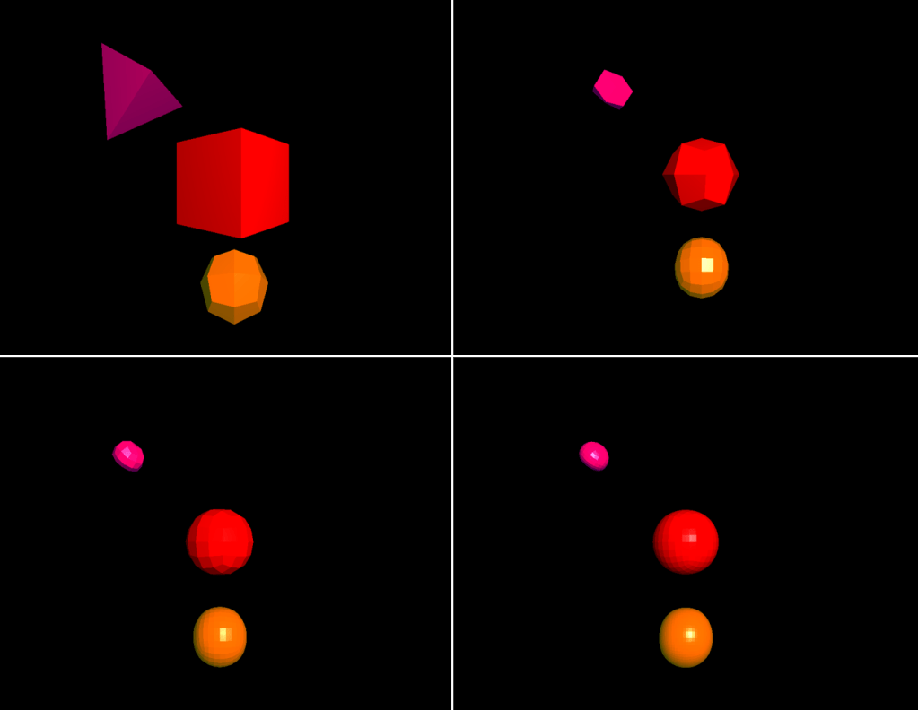
In this project, I have worked on reproducing the Catmull-Clark Subdivision Surface algorithm resides in this article. Given 3 different polygonal 3D .obj files, my goal was to smoothen the shapes by applying subdivision surface. In the rest of this blog, I will be explaining my objectives, my implementation details, and how I achieved my goal.
From this link you can watch my implementation video. Since I did a screen recording, the resolution is not perfect and does not reflect the real application at all. But it can give a glimpse of what this project is capable of.
The link to the Github repo can be found here. To run the application:
>> make
>> ./main
Reading .obj Files
In this project, user is flexible to increase and decrease the level of the algorithm randomly. This requirement introduces the calculation of new faces for each level from the faces on the previous level. Each new face operation brings along new face normal calculation since we need face normals to do light calculations. For these reasons, I am not intrigued by the vertex normal values in the .obj file. From this file, I have only extracted vertex positions, and vertex indices on each face, and stored them in vectors that hold Vertex and Face objects, respectively. Before storing the face, I have calculated face normals from the extracted vertex position values for each face.
Triangulating Quad Faces
OpenGL is instructed to draw triangles and lines. The given cube.obj file contains quad faces. Moreover, for each new level calculation, new faces will be generated as quad faces as in the algorithm logic. Thus, I triangulated each quad face before glDrawElements call to compatible with CCW facing direction for each face.
Finding edge points, face points, new vertex points
Calculations for finding edge points, face points and new vertex points were rather easy compared to shaping new faces from the new vertex values. I have just applied the necessary operations on edges and faces while storing the new values.
Shaping the New Faces From Recently Calculated Points
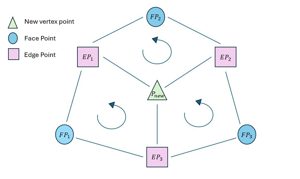
To find new faces, I have followed this path:
In each vertex, I have stored the new vertex point value inside, and the edges whose one of the vertex point is that vertex. In each edge, I have stored two faces in which this edge resides, and two vertices of this edge. Lastly, in each face, I have stored the edges and vertex indices of this face.

For each vertex, I have traversed their edges. For each edge of this vertex, the algorithm should choose the correct succeeding face to be compatible with CCW direction ie. the face should be front-facing. To achieve this, the below equation should hold:

Through following this approach, I have shaped my new faces. At the end of this process, faces are quad faces whose vertices are P_new, EP, FP, P_new. Before drawing them, each face is triangulated.
Flat shading
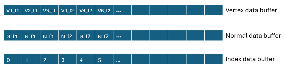
Flat shading ensures the same lighting and shading over each fragment of the face. It is usually implemented through compute shaders; however, we were instructed to do so with another way. For this reason, I have changed order of vertices and normals passed to the buffer data for drawing.
A vertex can be shared by many face, which means a vertex can have multiple normals while implementing flat shading. For these reasons, for each vertex in each face, I have added that vertex to vertexDataBuffer, and face normal to normalDataBuffer while changing the indexDataBuffer.
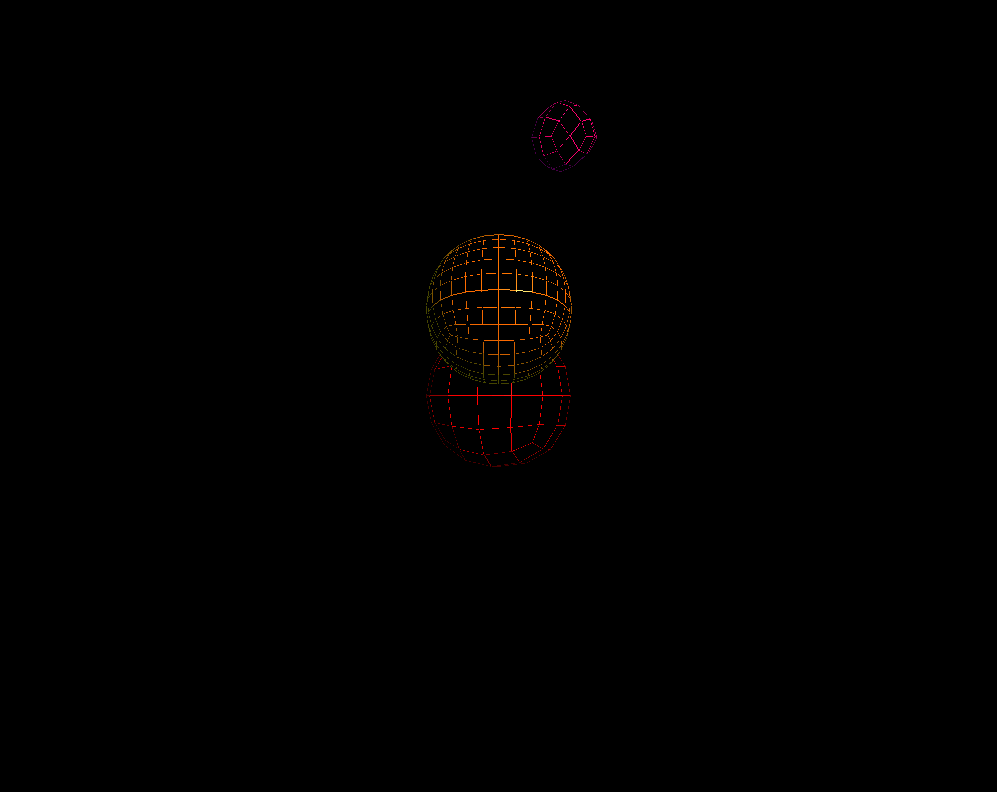
Wire Mode
For wire mode implementation, I have changed the content of buffer data to store edge vertices, normals, and indices. I have applied the same flat shading approach for wire mode in advance. For a smooth transition from solid mode to wire mode, I have stored the two modes’ buffer data in different VBOs and VAOs.

Line Mode – Objects Occluding Each Other
In the line mode implementation, I have used the same VAOs, and VBOs as wire mode. Different from wire mode, in line mode, objects should occlude each other while keeping the wire look. At first I have thought we should have been using frame buffers for two pass pipeline. However, we can achieve this result by simply on the first pass disabling writing to the color buffer while keeping depth test enabled, and on the second pass enabling writing to the color buffer.
This approach may lead to z-fighting as it occurred on my application. I could not figure out the exact polygon offset values to diminish the z-fighting as can be seen below. However, all objects occlude each other correctly, and their back faces are not visible.
Decreasing and Increasing Level
For increasing the level, the algorithm is called once. On the other hand, decreasing the level is not carried out with current level values. Instead, the increase level function is called (current level – 1) times on the initial shape. For example, if currently scene shows the level 5 and user wants to decrease the level by 1, the application starts from the base level values and increases the level until the targeted level.
Problems Encountered
A problem I have encountered during my implementation was that sometimes the objects were not occluding each other. This was due to my inappropriate two-pass draw call order. I mistakenly had applied two-pass draw call at once for each object rather than making the first-pass for all objects at first, and second-pass for all of them secondly. Fortunately, I have figured out the problem and fixed it.
What I spent most of my time is shaping new faces. I tried to come up with an efficient and fast algorithm. Hence, it took me more than I expected to finish this part.
Performance
| Level 0 | Level 1 | Level 2 | Level 3 | Level 4 |
| 150 fps | 144 fps | 140 fps | 140 fps | 140 fps |
