Introduction
In this homework, we were expected to implement the below operations:
- Equirectangular to cubemap face generation
- Median Cut Algorithm
- Tonemapping
I have managed to finish the first two of them. I have several attempts to achieve tonemapping. However, I could not configure the framebuffer. Throughout this document, I will explain the details of the program and the problems I encountered.
Equirectangular to Cubemap Face Generation
Firstly, one direction vector is generated for the back face of cubemap. By rotating the direction vector to point +x, -x, +y, -y, +z faces, 6 direction vectors are generated.
For each of the vectors corresponding phi, and theta values are calculated. Afterwards, phi and theta values are used to calculate (j,i) coordinates of the equirectangular HDR image. By sampling from original HDR image on these (j,i) coordinates, 6 cubemap textures are generated.
Problems Encountered
I had difficulty in understanding how to traverse the equirectangular image. Apparently, resolution of the cubemap faces should be decided. I arranged it as (height_cubemap, width_cubemap) = 1024 x 1024. Following this, the traverse should be
for (j: 0 -> 1023):
for (i: 0 -> 1023):
// implement the logic
After understanding the algorithm, I have generated the faces.
Another problem I managed to solve here was about the camera position. Even though I arranged the camera position to the center of the cube, once I orbit the camera around the center object, the camera could manage to see not only the front but also right, left, top, and bottom faces of the cubemap. It was a mistake due to the camera rotation radius. I fixed is once I identified.
Median Cut Algorithm
The program is designed to not exceed a median cut level of 7. I precalculated all the centroid values and stored them in a uniform buffer object that holds centroid positions and light values.
Finding Where to Split
The median cut algorithm is applied to the equirectangular HDR image. To apply the median cut to a region, we need to decide where to split the region, which should be along the longest side. The longest side is determined based on the j coordinate’s location. Pixel values decrease as we move from the center height line upwards or downwards. To determine the longest side, we check:
- If width * cos(φ) >= height, split along the width.
- Otherwise, split along the height.
cos(phi) is calculated by transforming j domain of [0, height – 1] to [- π, π] domain.
The below A matrix is a representation for HDR image. A matrix is composed of aji values where j ∈ [0, height – 1] and i ∈ [0, width – 1].
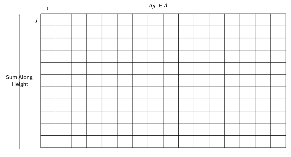
To find the cut line index when width * cos(φ) >= height, I sum along the height and write the values to another structure B of size 1 x width.
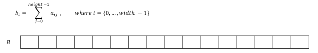
After that, I find another structure C of the same size of B by applying cumulative sum to B.

Now, the last element of the C holds the total sum of all elements. When we take half of it, we find the approximate value of the each new region. By applying binary search on C matrix to find in which interval this halved value resides, I managed to find the median cut split index.
The same operations applied to the “split from height” case, but instead the sum is calculated over width.
Finding the Centroids
I find the centroids by calculating the weighted sum of each region. The result of this operation gives only the i and j coordinates. However, we need φ and θ spherical coordinates. Utilizing i, j, and width, height values I found them through conversion equations.
Region Light Value
Each region’s light value is calculated by taking the sum of its pixel values’ cos(φ) scaled versions.
I applied the median cut algorithm 7 times and send the centroid values to fragment shader as uniform buffer object.
Tonemapping
I could not applied tonemapping. There were problems in adjusting frame buffer. Here is an example problem image from my trials:

I have also faced another problem. When I enabled DEPTH_TEST, frame buffer texture does not show anything on the screen. I could not find the problem and I left the rest of the homework untouched.
Other Problems
I could not rotate the camera around the center object properly. That’s why the light positions on the object does not reflect the reality that much when we orbit around the center object.
Here you can find the false camera rotation example and the effect on the program. The light positions seems to always face the other side.
Conclusion
Here is a video of the overall program.
